 Photo Diode 3mm

 LED display and diode manufacturer,Betlux
LED digital world, share with you the quality LED technology
LED display and diode manufacturer,Betlux
LED digital world, share with you the quality LED technology
Photo Diode 3mm
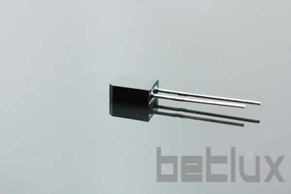
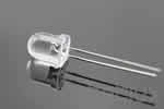
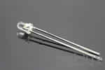
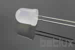
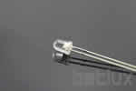
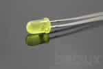
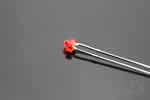
3522 Silicon Photo Diodes
BL-L3522PD
Photo Diode 3mm
| Brand | BETLUX |
| Part NO | BL-L3522PD |
| Dimension | 5.10*3.00*7.40 mm |
| Weight | 0.1700g |
| Package | 1000 |
| Datasheet |  |


Feature:
Description
;5.1*3.0*7.4mm SILICON PHOTO DIODES
;Choice of various viewing angles.
;Diffused and Water clear lens are available.
;Fast response time.
;High photo sensitivity.
;Small junction capacitance.
;The epoxy package itself is an IR filter, spectrally
RoHs Compliance


Electrical-optical characteristics:
Package configuration & Internal circuit diagram
Tolerance is +-0.25(0.01") unless otherwise note
Specifications are subject to change without notice.
Absolute maximum ratings (Ta= 25?C)
Partno description:
Related Information
Applied for:


The LEDs described here are intended to be used for ordinary electronic equipment (such as office equipment,
communication equipment and household applications). Consult Betlux's Sales in advance for information on
applications in which exceptional reliability is required, particularly when the failure or malfunction of the LEDs
may directly jeopardize life or health (such as in aviation, transportation, traffic control equipment, medical
and life support systems and safety devices).
CAUTIONS for Through-Hole LED Lamps
1. Application
The LEDs described here are intended to be used for ordinary electronic equipment (such as office equipment,
communication equipment and household applications). Consult Betlux's Sales in advance for information on
applications in which exceptional reliability is required, particularly when the failure or malfunction of the LEDs
may directly jeopardize life or health (such as in aviation, transportation, traffic control equipment, medical
and life support systems and safety devices).
2. Storage
The storage ambient for the LEDs should not exceed 30℃ temperature or 70% relative humidity. It is
recommended that LEDs out of their original packaging are used within three months
For extended storage out of their original packaging, it is recommended that the LEDs be stored in a sealed
container with appropriate desiccant or in a desiccator with nitrogen ambient.
3. Cleaning
Use alcohol-based cleaning solvents such as isopropyl alcohol to clean the LED if necessary
4. Lead Forming & Assembly
During lead forming, the leads should be bent at a point at least 3mm from the base of LED lens. Do not use
the base of the leadframe as a fulcrum during forming.
Lead forming must be done before soldering, at normal temperature.
During assembly on PCB, use minimum clinch force possible to avoid excessive mechanical stress.
Soldering
When soldering, leave a minimum of 2mm clearance from the base of the base of the lens to the soldering point. Dipping the lens into the solder must be avoided.
Do not apply any external stress to the lead frame during soldering while the LED is at high temperature.
Recommended soldering conditions:
| Wave Soldering | Soldering Iron | ||
| Pre-Heat | 100°C Max. | Temperature | 300°C Max. |
| Pre-Heat Time | 60sec Max. | ||
| SolderWave | 260°C Max. | Soldering Time | 3sec Max.(one time only) |
| Soldering Time | 5sec Max. | ||
Note: Excessive soldering temperature and/or time might result in deformation of the LED lens or failure of the LED
Static Electricity or power surge will damage the LED.
Suggestions to prevent ESD damage:
Use a conductive wrist band or anti-electrostatic glove when handling these LEDs
All devices, equipment, and machinery must be properly grounded
Work tables, storage racks, etc. should be properly grounded
Use ion blower to neutralize the static charge which might have built up on surface of the LED's plastic
lens as a result of friction between LEDs during storage and handling
ESD-damaged LEDs will exhibit abnormal characteristics such as high reverse leakage current, low
forward voltage, or “light off” at low currents. To verify for ESD damage, check for “light on” and Vf
of the suspect LEDs at low currents.
The Vf of “good” LEDs should be>2.0V@0.1mA for InGaN product and >1.4V@0.1mA for AlInGaP product
Drive Method
An LED is a current-operated device. In order to ensure intensity uniformity on multiple LEDs connected in
parallel in an application, it is recommended that a current limiting resistor be incorporated in the drive circuit,
in series with each LED as shown in Circuit A below.

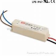
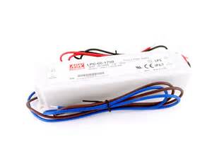
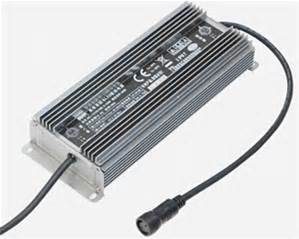
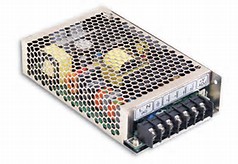
Power source for LEDs (5v/12v/24v AC/DC converter, DC/DC converter, waterproof/non-waterproof)
Related Products
 LED light bar (circle,20mm big LED)
Sales price:
|
 8mm LED diode
Sales price:
|
 3mm LED diode
Sales price:
|
 10mm LED diode
Sales price:
|
 4mm LED diode
Sales price:
|
 5mm LED diode
Sales price:
|
 1.8mm super bright LED diode
Sales price:
|
Related Categories
 SMD LED |
 power LED |
 Oval LED |
 IR LED |
 PHOTO DIODES |
 PIRANHA LED |
 BLINKING LED |
 MULTI-COLOR LED |
 LED bullet |
 SUPER BRIGHT LED |
SMD LED |
power LED |
Oval LED |
IR LED |
PHOTO DIODES |
PIRANHA LED |
BLINKING LED |
MULTI-COLOR LED |
LED bullet |
SUPER BRIGHT LED |